Node Set Manager
VCollab Pro users can group a set of nodes and use it in other functional modules using the Node Set Manager option under CAE menu. This reduces significant time in selection of nodes for different purposes.
Node Set : A Node Set is a group of nodes having a name given by the user.
A Node set can be used in
masking color plot
vector plot
XYPlot
Hotpot finder
Node Set Manager Panel
Click CAE|Node Set Manager to open the panel as shown below. There are three tabs , Creator tab, Manager tab and Filter Save tab.
Creator Panel
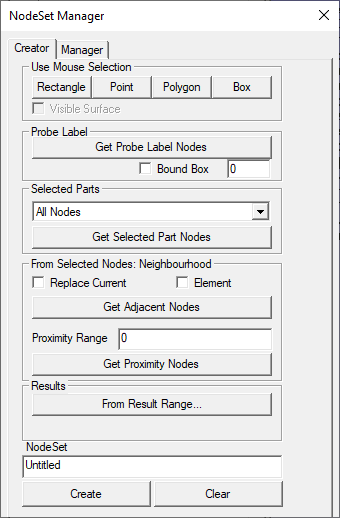
The various fields and options in the Creator tab are explained below.
Selection using mouse |
|
Rectangle |
Allows user to select nodes by user window |
Point |
Allows user to select nodes by picking |
Polygon |
Allows user to select nodes by user polygon |
Box |
Allows user to select a region by mouse and modify the box dimensions. |
Visible Surface |
A filter option to ignore hidden nodes. |
Get Probe Label Nodes |
Selects all visible probed node IDs. |
Bound Box |
A bound box with given distance is considered at each probe label. All nodes within each box are considered for node set. |
Selection using highlighted parts |
|
Selection Parts |
User can choose any one of the following options.
|
Get Nodes |
Gets filtered nodes according to the selected constraint. |
Selection using current selected nodes |
|
Replace Current |
Clears existing nodes and considers new neighborhood or proximity nodes. |
Element |
Considers adjacent element instead of adjacent nodes |
Get Adjacent Nodes |
Appends immediate adjacent nodes of current nodes. |
Range |
Proximity radius value of Node or element. |
Element Proximity |
A On/Off flag for Element or nodal proximity. |
Get Proximity Nodes |
Appends nodes within the proximity range. |
From Resut Range... |
Pops up result range dialog, user can select scalar result and set range. This function selects all the nodes those scalar result value falls within the user range. |
Node set Name |
Name of the new node set. |
Create |
Creates a node set with user defined name and final nodes displayed currently. |
Clear |
Clears displayed nodes. |
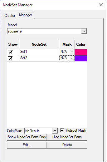
Manager Panel
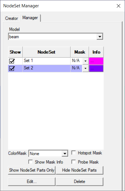
The various fields available in the Manager tab are explained below.
Model |
Selects a CAE Model |
List Box |
Lists all node set names corresponding to the model |
Show |
Check/Uncheck to show/hide |
Node set |
Node set name mask for hotspot finder or color plot |
Mask Type |
Allows user to select mask type. (Inside or Outside or None are the types) |
Info |
Clicking on '...' pops up nodeset info dialog. |
Color Mask |
Masking the node sets in contour. |
Hotspot Mask |
Masking the node sets in finding hotspots. |
Show Mask Info |
Displays Masking info in CAE Legend. |
Probe Mask |
Masks probe in the nodeset if enabled. |
Show NodeSet Parts Only |
Displays parts associated with nodesets. And Hides other parts. |
Hide NodeSet Parts |
Just hides the parts associated with the nodeset. |
Edit |
Allows user to edit the nodeset. |
Delete |
Delete all selected node sets. |
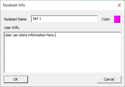
Nodeset Info Panel
This panel is invoked when user click on the cell under Info header. This helps users to rename the nodeset, edit the color and add and store user information for the particular nodeset.
Nodeset Name |
Allows to edit nodeset name and store. |
Color |
Allows user to edit the color and save. |
User Info |
Allows users to add and store information for a particular nodeset. |
OK |
Closes dialog and apply the modifications to parent dialog. |
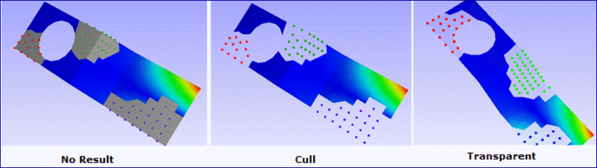
Types of Color Mask
VCollab provides following types in color masking.
None - No masking
No Result - Masked region will be in 'No Result' color
Cull - Masked nodes and its associated elements will not be displayed.
Transparent - Masked region will be displayed as semi transparent.
Steps to create a Node Set
Selection of Nodes
Click CAE | NodeSet Manager... menu item, which pops up a dialog.
Click a mouse selection mode, Rectangle / Point / Polygon.
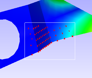
Rectangle mode
Use left mouse button to drag a window to select nodes.
Use right mouse button to drag window to deselect nodes.
Point mode
Click on a node directly to select it.
Click a selected node with the middle button to deselect it.
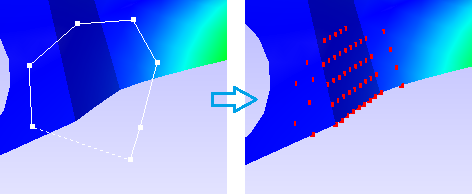
Polygon mode
Left click start defining a polygon.
Click points on the screen to build a polygon.
Right click to close the polygon.
The selected nodes are displayed in the viewer.
Use the Visible Surface option to filter hidden nodes in the current view.
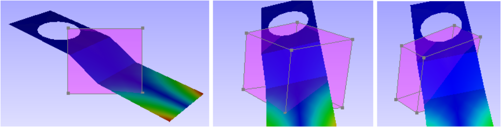
Box
Use left mouse to click and drag to define a box.
Each bound plane can be moved in or out using mouse click and drag.
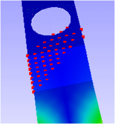
Click the box button again to complete node selection within the box. Box will dissappear and nodes will be highlighted.
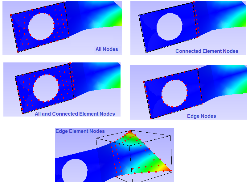
Appending Nodes from selected parts
Select parts before using this option.
Select
All Nodes to get all the nodes from the selected parts.
Connected Element Nodes to get nodes from the elements which connect selected parts and other parts.
All and Connected Element Nodes to get all nodes from selected part and connected element parts.
Edge Nodes to get nodes on the feature edges of selected parts. This depends on feature edge crease angle too.
Edge Element Nodes to get nodes from the elements of which has at least one feature edge.
Click Get Nodes to append the nodes.
Appending Nodes from probe
Click the Add Probe Labels button to include all probed nodes.
Select Visible Probe Labels option to ignore hidden probe label nodes.
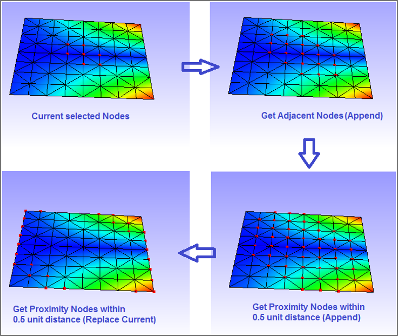
Appending or Replacing selection using 'From Selected Nodes : Neighbourhood'
Click the Get Adjacent Nodes button to find adjacent nodes of selected nodes.
Use Proximity Range to find nodes which falls within a given range of selected nodes.( i.e. Nodal Proximity)
Select Element Proximity to find nodes which fall within a given range of elements (associated with selected nodes).
Click Get Proximity Nodes to append the selection of nodes.
Click Replace Current option to replace the selection instead of appending.
Clearing the selection
Click Clear to clear the current selection of nodes.
Creating Node Set
Provide a unique name to the selection of nodes (node set) in the text box given
Click Create to create a node set whose name will be added to the list in the manager tab.
Steps to manage Node Set list
Created Node Sets as explained above.
Click CAE | NodeSet Manager... to open the NodeSet Manager panel.
Select Manager tab.
Select the CAE model for which node sets need to be managed
Select a node set name.
Editing Node Set
Click Edit to
modify the nodes in the set.
Clear and build new node set, Or
Filter nodes by removing nodes.
Deleting Node Sets
Select a Node Set to be removed.
Click Delete.
Toggling Node Set Attributes
Click the Show check box in the Node Set list box to turn On / Off its visibility.
Click the Mask check box in the Node Set list box to mask / unmask color plot for those nodes.
Click Color cell to edit display color of the nodes.
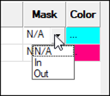
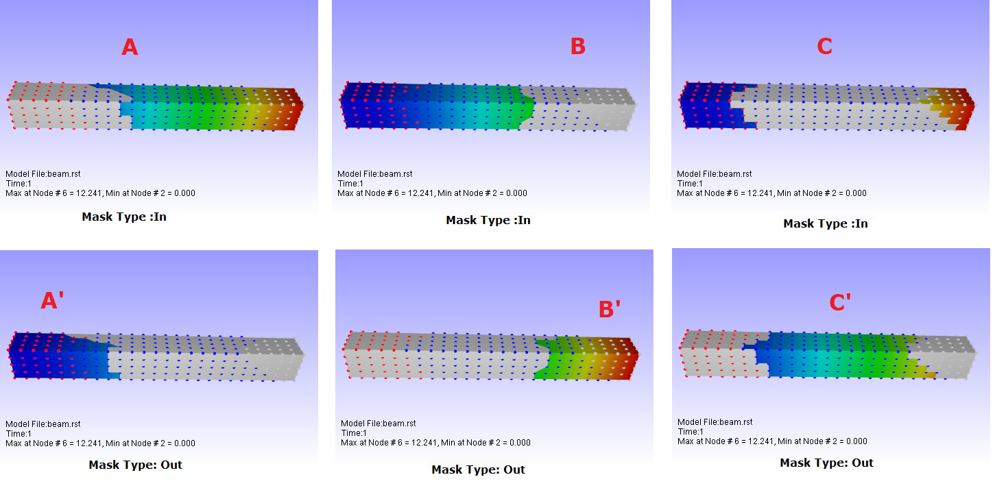
N/A refers to 'No Masking'
It refers to include in masking.
Out refers to exclude the nodeset from masking.
Click Color cell to edit display color of the nodes.
Click Mask check box in the bottom of dialog to mask / unmask the color plot for those nodes.
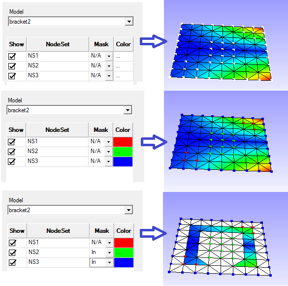
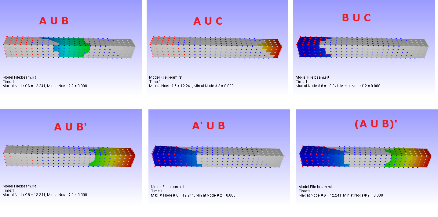
Combination of In and Out masked Nodesets
Nodeset A with In mask type is refered as A Nodeset A with Out mask type is refered as A'
Node Sets in Hotspot Finder
Open Hotspot Finder Settings tab under CAE Settings
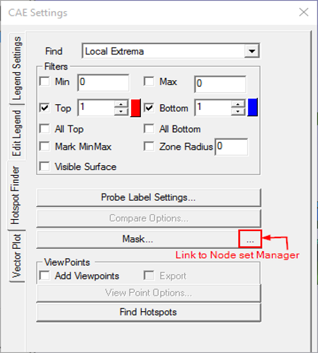
Click Mask...to open the dialog below where one can select or deselect Node Sets.
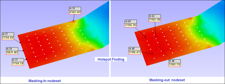
Masking is not supported for Elemental Result.
Users can select multiple Node Sets for masking during hotspot finding operation.
Steps for creating a nodeset from the result range
Open Nodeset Manager dialog.
Click Creator tab
Click the From Result Range... button to open the dialog box as shown below
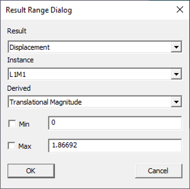
Select the required Result, Instance and Derived scalar result.
Check Min and Max check boxes and edit their values
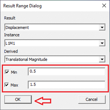
Click OK
Nodes within the result range will be highlighted in the viewer.
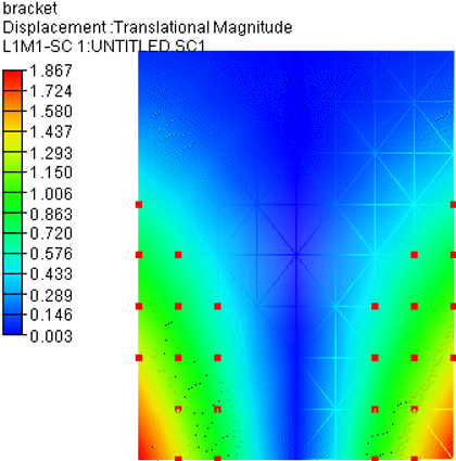
Click the Create button to create the nodeset.