Label
Labels are added by users for better understanding of product features and parts. VCollab Presenter users can add, format, delete, move and fit a label or annotation to any part using the Label option found under the context menu.
Label Option in Context Menu
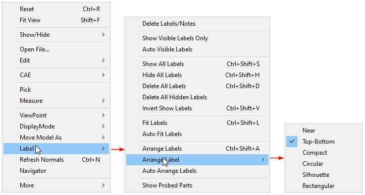
The various options found under Labels/Notes are explained below
Delete Labels/Notes |
Deletes user selected label or note. |
Show Visible Labels Only |
Displays visible labels only |
Auto Visible Labels |
Shows visible labels only dynamically during user interaction. |
Show All Labels |
Shows all labels independent of attached position visibility |
Hide All Labels |
Hides all labels |
Delete All Labels |
Deletes all existing labels |
Delete All Hidden Labels |
Deletes all hidden labels. |
Invert Show Labels |
Inverts the labels visibility. |
Fit Labels |
Fits all labels inside view port |
Autofit Labels |
Fits all labels inside viewport automatically during motion model |
Arrange Labels |
Arranges all labels in an order. It has three mechanisms, Near to attached position, top-bottom method, Compact, rectangular, Circular and Silhouette. |
Auto Arrange Labels |
Arranges all labels automatically whenever the user modifies the label or table dimensions. |
Show Probed Parts |
Hides all parts except the probed parts. |
Label Settings Panel
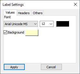
The various tabs and fields available in the Label settings panel are explained below.
Values tab |
Applicable for CAE Probe label value cells. |
Headers tab |
Applicable for CAE Probe label header cells (Row header, Column header and Header Legend table) |
Others tab |
Applicable for measurement labels. |
Font |
Lists font face names for user selection. |
Font Size |
Lists font size values from user selection. |
Text Color |
Allows to change text color. |
Background |
Allows to set and modify background color. |
Line width |
Allows the user to edit the width of the line between label and part. |
Border |
Allows to set and modify border color. |
Line Color |
Allows to pick color for extended line between part and label. |
Transparent |
Allows users to set and modify transparency and its value. |
Keep Previous Labels |
Keeps old labels. |
Show ID |
Displays node or element IDs in the label. |
Header Field |
Applies the user modifications to header cells of probe labels. |
Steps to create a label or note for a specific part
Click Tools | Add Notes..
The Add Notes dialog box opens up. Check the option Attach Geometry.
Enter your note in the edit text box provided
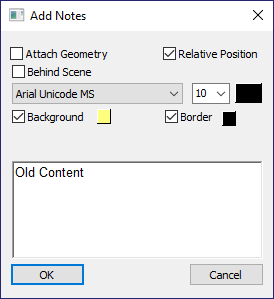
Select the font, size and color for the text.
Check or uncheck Background and Border options if necessary. Select the color for Background, Border and Text from the corresponding color window.
Click Behind Scene to send the label behind models. This option is ignored for labels with attach geometry.
Click OK.
Click in the viewer window to place the label as required.
A connecting line is visible between label position and mouse pointer.
Click a point on the specific part. The label will be seen attached.

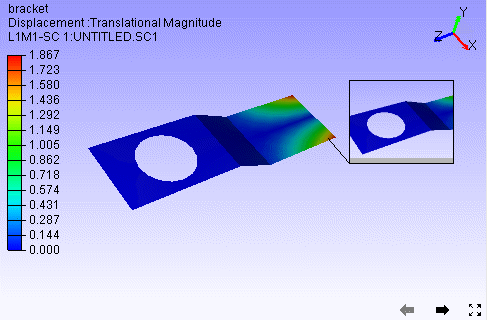
Below is an example of a label behind the model.
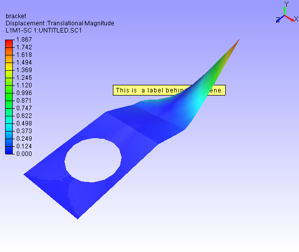
Note
Behind Scene option is applicable only for 2D labels and tables.
Steps to edit labels or notes
Double click on a label to open Edit Notes dialog box
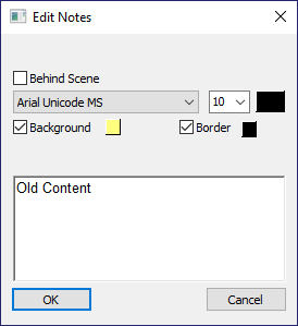
Edit the contents and formats.

Click OK
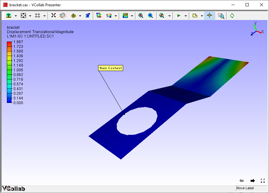
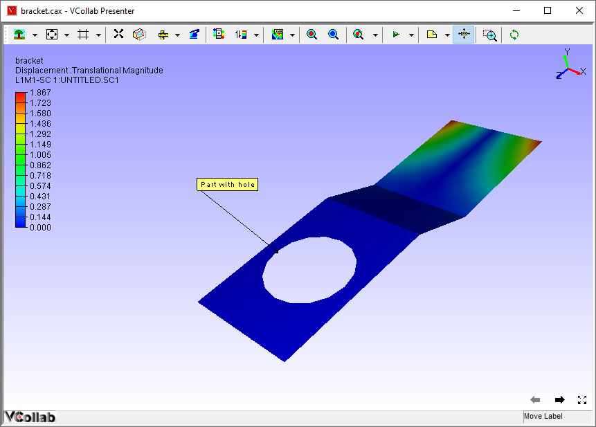
Steps to move an existing label
Click Move Labels/Notes icon
 available in the toolbar to
enable it.
available in the toolbar to
enable it.Drag the concerned label or annotation in the viewer.
Release the mouse after the label position is shifted.
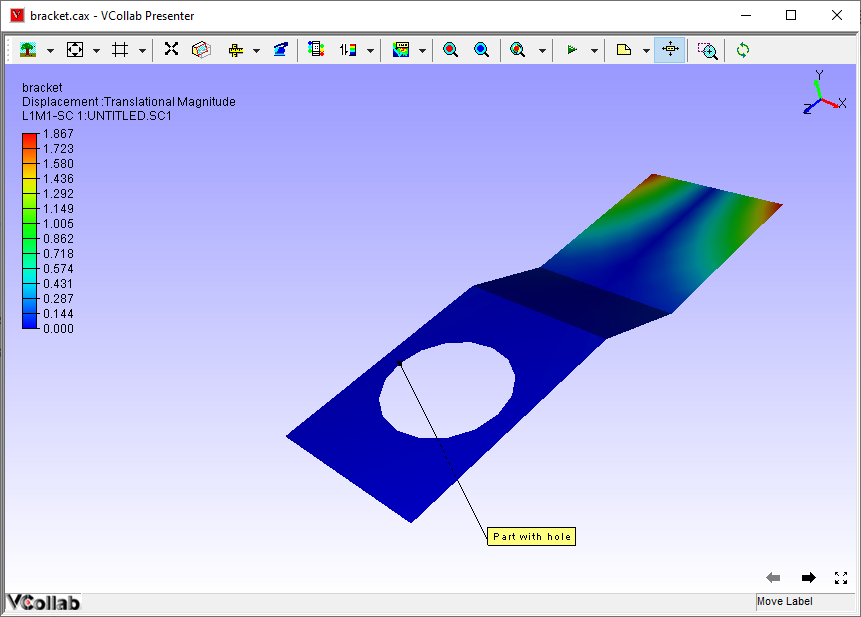
Click the Move Labels/Notes icon
 again to disable it.
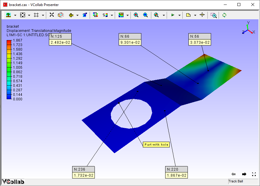
Steps to Fit Labels inside the viewer
Click Label | Fit Labels option to fit the labels inside the viewer.
Before
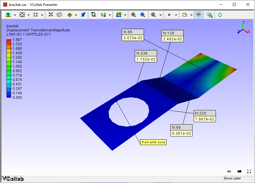
After Fit Labels
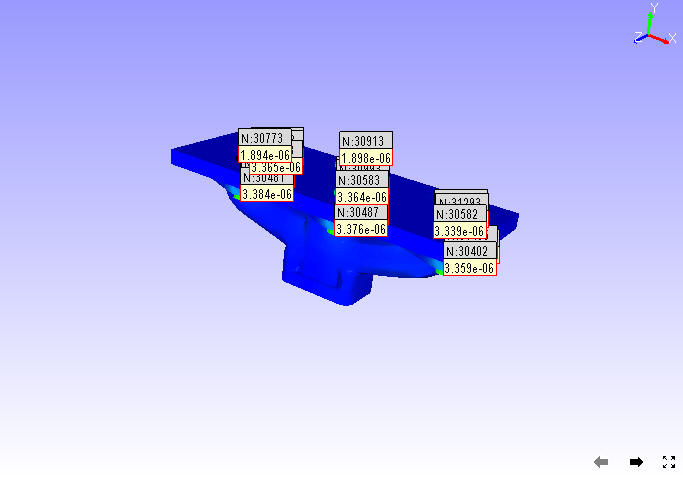
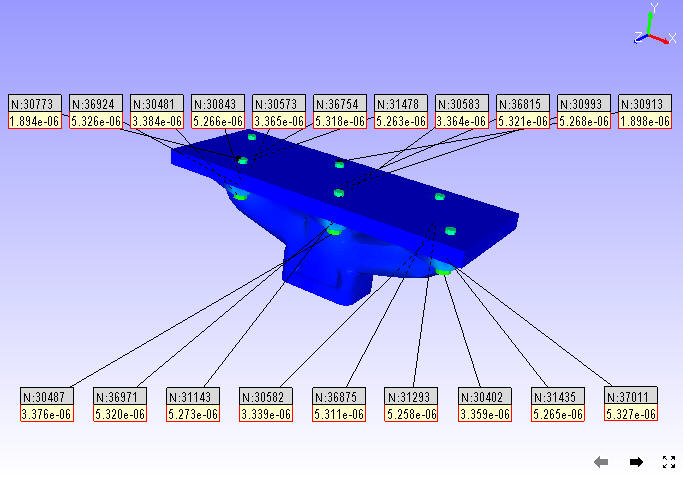
Steps to avoid label overlapping
There is a possibility of overlapping of multiple labels in hotspot finder. It can be avoided using the option Label | Arrange Labels.
Load a CAX model.
Select CAE | CAE Settings option from context menu to open the CAE Settings dialog.
Click the Hotspot Finder tab.
Set top and bottom count to 10 each.
Close the CAE Settings dialog.
Click the Hotspot Finder icon in the toolbar.
Select an area in the viewer.
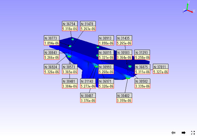
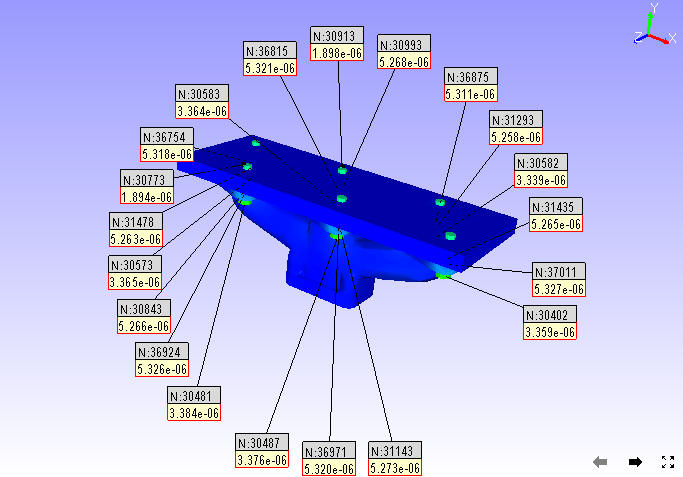
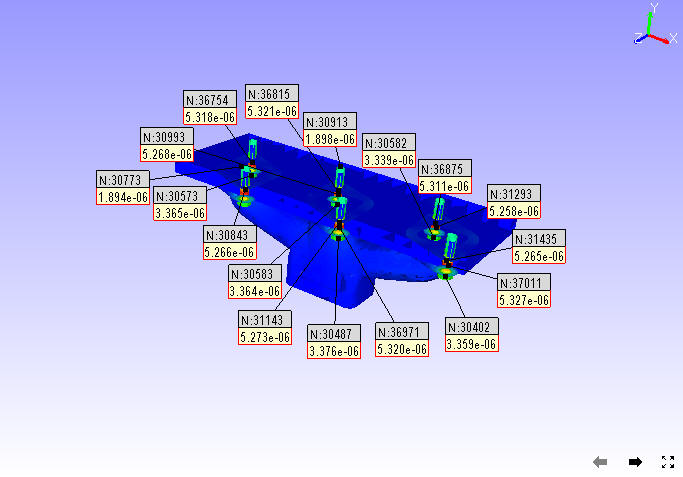
Notice that multiple labels are overlapping each other.
Click Label | Arrange Labels.
The labels are arranged in an order and none overlaps each other.
Steps to delete a label
From the context menu, click Label | Delete Labels/Notes
Click on a label to be deleted
Click Label |Delete All labels to delete all labels at one go.
Steps to Show/Hide a label
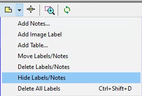
Click Tools | Labels/Notes | Hide Labels/Notes.
Click on a Label.
Clicked label is hidden.
Use the Label list panel to show it again.
Select the label in the label list.
Click the visibility check box in the panel to show the label again.
Difference between 'Show Visible Labels Only' and *'*Auto Visible Labels'
These options are applicable only for probed labels and annotated notes. These labels contain two positions, one is label position and the other is attached position in the geometry. Based on these attached positions' visibility in the current view, labels can be classified as Observable and Non-Observable labels.
The attached positions of Observable Labels are visible in the view.
The attached positions of Non-Observable Labels are hidden behind geometry surfaces in the view.
Users can hide the Non-Observable labels if necessary using the options 'Show Visible Labels Only' and 'Auto Visible Labels'.
'Show Visible Labels Only' hides the Non-Observable labels for the current view. This is a one time event.
'Auto Visible Labels' hides Non-Observable Labels and shows Observable Labels dynamically according to the view.
Methods of Arranging Labels
Near: This method repositions all labels and tables very close to the actual label attached positions.
Top-Bottom: This method splits the labels into top and bottom labels and places them based on attached positions.
Compact: This method searches for a possible zone around the label attached position and allocates them without label overlapping.
Circular This method searches for a possible zone around the label attached position and arranges them in a circular manner without overlapping.
Silhouette: This method searches for a possible zone around the label attached position and arranges them along the model outline without overlapping.
Rectangular: This method searches for a possible zone around the label attached position and arranges them in a rectangular manner without overlapping.

Ranking Probe Labels
Probe labels are ranked based on current contour scalar results in descending order by default. Users can reverse the ranking process and make it ascending, i.e., Lowest value will be ranked first. Labels having equal values are given the same rank.
Note: Ranking is applicable only for current derived probe type labels.
Select probe type as Current Result - Derived type.
Probe a few values.
Click Tools | Labels / Notes | Rank Probe Labels.
All labels are ranked and displayed with rank number.
Click CAE | Probe Settings ...
Uncheck or check the Rank Ascending Order option to reverse the ranking process.
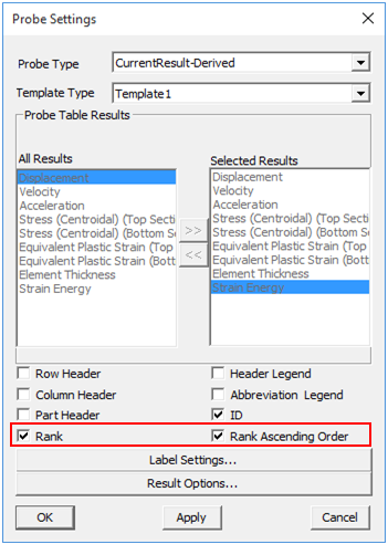
Rank numbers will be reversed.
Adding Tables
Click the dropdown menu next to the Add Notes icon in the toolbar.
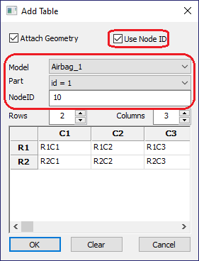
Click the Add Table option to open up Add Table dialog box.
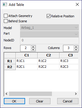
Define the number of rows and columns.
Double click the cell to edit the contents. For example,
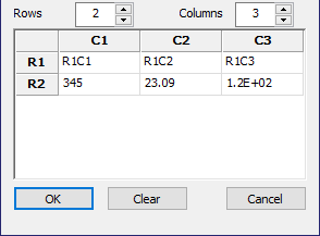
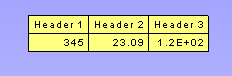
Enter the texts and click OK.
Click on the viewport to see the table as below.
Relative Position and Attach Geometry options function the same way as in the Add Notes annotations.
Enabling Attach Geometry option displays Use Node ID options. It helps the user to enter model, part and node ID to be attached with.
To edit a table, double click on the specific table to open the Table context menu
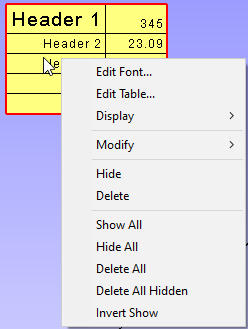
Edit Font.. allows the user to edit font name, size, background etc. same like in probe table, except the Update All Viewpoints option.
Edit Table... opens up Edit 2D Table or Edit 3D Table dialog box based on Attach Geometry option.
Display allows the user to transpose the table and to highlight the table.
Modify allows the user to add, delete and insert columns or rows.
Context menu for 3D Table is slightly different from the 2D Table context menu.
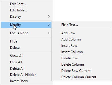
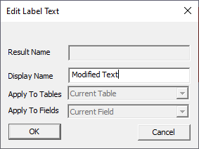
Modify | Field Text... allows me to edit current cell text.
Focus Node focuses on the attached location of the label.
Image Annotation
User can add images into annotation labels using 'Add Image Labels' option.
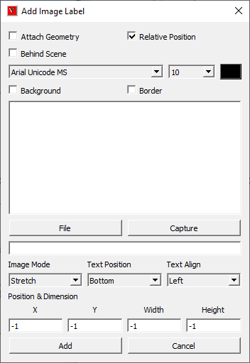
Attach Geometry |
Allows user to attach this image label to a point on the model. |
Behind Scene |
Allows user to send the 2D Image Labels behind the model. This flag will be ignored if Attach Geometry is ON. |
Relative Position |
When Attach Geometry is checked, then Relative Position check appears. Relative Position stores position of label relative to window and changes accordingly with window resize. |
Font and Text |
Allows user to select font name, font size and text color for label text. User can enter the text in the box if required. |
Background and Border |
Allows user to choose to apply background and border colors. |
File |
Allows user to pick an image file from the disk. |
Capture |
Allows user to capture image from the viewer window. |
Model Only |
Allows user to capture the model with transparent background, while using 'Capture' option. |
Auto Resize |
If this option is true, then a change in viewport dimension makes a relative change in label dimension. |
Image Mode |
Allows user to select image mode from the list Center, Stretch and Fit View options. |
Text Position |
Allows user to place text in the top or bottom of label (above or below the image) |
Text Align |
Allows user to align the text horizontallly from left, center and right optios. |
Pixels |
Displays position and sizes in actual pixels. Otherwise it displays on normalized values, i.e (0.0 to 1.0). |
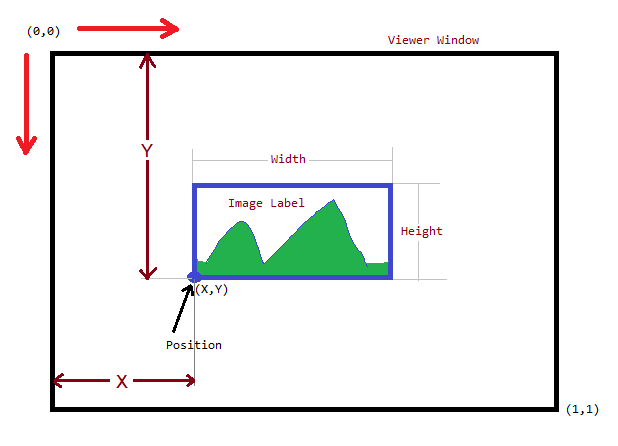
Position |
Allows user to set position directly using normalised screen coordinages i.e. position (x,y) values varies between 0 and 1. |
Dimension |
Allows user to set the dimension of the image label panel using normalized width and height. |
Add |
Adds the image lable in viewer accordingly. |
Cancel |
Cancels all settings and closes the panel. |
Normalized Position and Dimension
Steps to add Image labels
Click the dropdown menu located at the end of Labels tool bar.
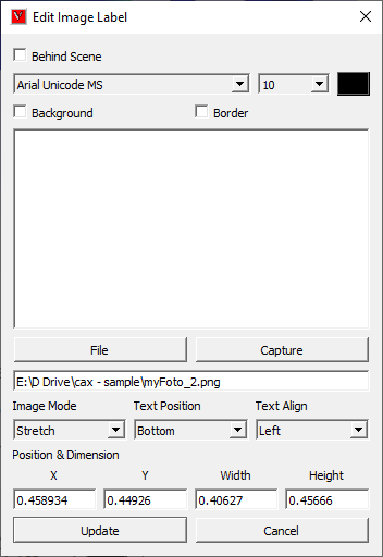
Click "Add Image Labels..." option to pop up Add Image Label dialog.
Enter text if required.
Click 'File' button to select an image file from the computer.
Click 'OK' in the file browser dialog. Or
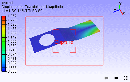
Click 'Capture' button to get the image from the viewer.
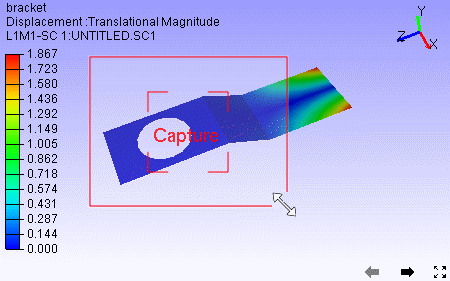
Panel disappears and a rectangular window appears in the viewer.
User can resize and move the window as required.
Click 'Capture' zone in the window.
Add Image panel appears again.
Image file path should appear in the text box below 'File' button.
Change Image Mode, Text Position and Text Align options if required.
Click 'Add'
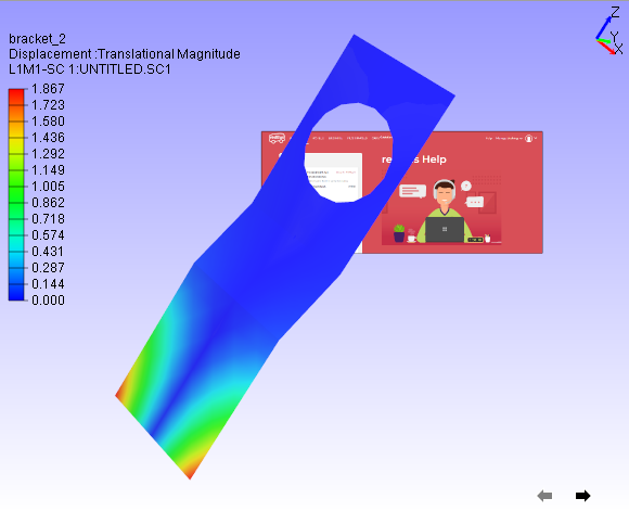
Click on the model if 'Attach Geometry' was checked.
Click on the viewer anywhere if 'Attach Geometry was unchecked.
Now label with image will be displayed.
Steps to edit Image label
Double click the Image label.
Edit Image Label panel pops up.
User can modify the image using 'File' and 'Capture' options.
Click 'Update' button to apply the modifications.
Rich Text Labels
Using Rich Text labels, User can format the content in a html editor. Interface for this option is provided in the drop down menu under the User notes toolbar as below,

Rich Text Panel

Background and Border |
Allows user to choose to apply background and border colors. |
Compact |
Crops the Image to fit the text. |
User Values |
A flag to be used to enable image width and height options for user values. |
Wi and Hi |
Wi and Hi are width and height of the image to be captured. |
Behind Scene |
Allows user to send the 2D Rich Text Labels behind the model. This flag will be ignored if Attach Geometry is ON. |
Image Mode |
Center,Stretch,Fit View and Actual. By default all the rich table content as Image with Actual option. |
Attach Geometry |
Allows user to attach this label to a part/model. |
Auto Resize |
If this option is true, then a change in viewport dimension makes a relative change in label dimension. |
Relative Position |
When Attach Geometry is checked, then Relative Position check appears. Relative Position stores position of label relative to window and changes accordingly with window resize. |
Pixels |
Displays position and sizes in actual pixels. Otherwise it displays on normalized values, i.e (0.0 to 1.0). |
Label Size |
Allows user to control the dimension of the rich text label window to be updated with user given W,H values or not. |
W,H |
User defined width and height of the generated image. |
X,Y |
User defined position of the rich text label. Valid values are between 0 to 1 (normalized). |
OK |
Adds the image lable in viewer accordingly. |
Cancel |
Cancels all settings and closes the panel. |
Steps to Rich Text Labels
Click User Notes drop down menu and click Add Rich Text Labels
It pops up Add Rich Text Label dialog, with Rich Text Editor.
All the menu and toolbar options in the dialog are self explanatory to format the content.
Modify Background and Border using the popup windows if required.
Click OK and wait for a status bar message in the main window.
Follow the instruction appears in the status bar.
Click on the screen where ever user wants.
Label will be positioned there.

Double Click on the label to be edited.
Edit Rich Text Label dialog will pop up.

Check Behind Scene option to send the label behind the model.

Check Compact to make the content compact.

UnCheck Background and Border options.
