List of Commands
General Commands
SAVE
This command saves the 3D Report into various formats as listed.
SAVE, <HTML/WCAX/CAX/PDF>, <Output File Name>
[1] Option
HTML
WCAX
CAX
PDF
[2] Output file name (optional): By default, it will take same name as native file name
Examples
Saves the CAX report with the same name as native file name.
SAVE,CAX
Saves the HTML file with the same name as CAX file name.
SAVE,HTML
CUR_FOLDER
This command sets default Folder Path for files.
CUR_FOLDER,<CAX/PY/TEMP> or <Path>
[1] Option
CAX: Cax file path is set as current folder
PY: Script file path
TEMP: VCollab Temp path or or log file path
<Path>: Enter full path
LOADCAX
This command opens the CAX file from the specified.
LOADCAX, <CAXFilePath>
[1] Cax file path: of the file to be loaded
MERGECAX
This command merges the CAx file into the current used CAx file.
MERGECAX, <Merge_CAXFilePath>
[1] Cax file path: of the file to be merged
SET_VAR
Define list of variables.
SET_VAR,<variable_name>=<variable Value>
Examples
Defines a variable A which is assigned a VCollab Instance L3M1.
SET_VAR,A=L3M1
Defines a variable VMStress_Limit which is assigned a value of 390.
SET_VAR,VMStress_Limit=390
PARAMETER
Define parameter of selected type with name and optional default value.Used for executing parameterised templates interactively. See here.
PARAMETER,TYPE,Name or Key,<Default Value>
[1] TYPE: If none of the options below are chosen, TEXT is the default.
TEXT
PARTS
MODEL
RESULT
INSTANCE
NODESETS
FOLDER
FILE
FILE_CAX
FILE_IMG
ASM: Assembly
CAMERA_VIEW
CAMERA_XYAXIS
VPINDEX: ViewPoint Index
VPNAME: ViewPoint Name
PART: Single
MODELS: Multiple
RESULTS: Multiple
INSTANCES: Multiple
NODESET: Single
ASMS: Assembly Multiple
[2] Key or Parameter Name
[3] Default value
Examples
Defines a variable PARTS2SHOW which is assigned default value *part1*.
PARAMETER,PARTS,PARTS2SHOW,*part1*
SHOWCMDS
Popup Display commands (for debugging).
SHOWCMDS, <Y/N>
[1] bShowCmds: Set Y to show popups
SET_MODEL
This sets model as current.
SET_MODEL, <model Name>
[1] Model name
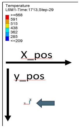
AXIS_POS
This sets the postion of axis on the screen based on X and Y position.
AXIS_POS, <X position>, <Y position>
[1] X position: increases from left to right on the screen
[2] Y position: increases from top to bottom on the screen
<X position> and <Y position> can be floating values
Set Camera Commands
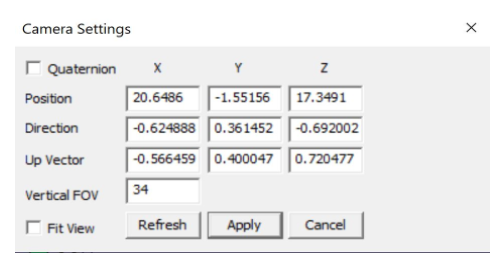
CAMERA_VIEW
This command sets the view direction (or camera Z direction vector <dx,dy,dz>) and Up-vector <ux,uy,uz>.
CAMERA_VIEW, dx, dy, dz, ux, uy, uz
[1:3] Camera Z-Dir
[4:6] Y-Dir Up Vector
This command specifies camera orientation of a model in VCollab Pro GUI.
Example
CAMERA_VIEW,-0.63,0.36,-0.69,-0.57,0.4,0.72
CAMERA_XYAXIS
This command sets Camera axis X-dir and Y-Dir (Upvector).
CAMERA_XYAXIS, dx, dy, dz, ux, uy, uz
[1:3] X-Dir
[4:6] Y-Dir Up Vector
Example
CAMERA_XYAXIS,1,0,0,0,1,0
FIT_VIEW
This command zooms the model view in VCollab Pro GUI.
FIT_VIEW, <zoom factor>
[1] zoom factor (optional): Varies from -0.5 to +0.5, default is 1.0
Example
It fits the model view in VCollab Pro GUI.
FIT_VIEWIt fits the model view in VCollab Pro GUI with a zoom factor of -0.3.
FIT_VIEW,-0.3
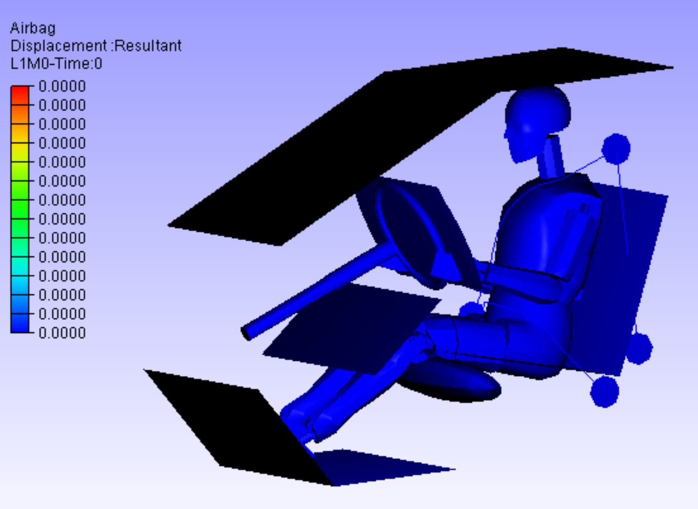
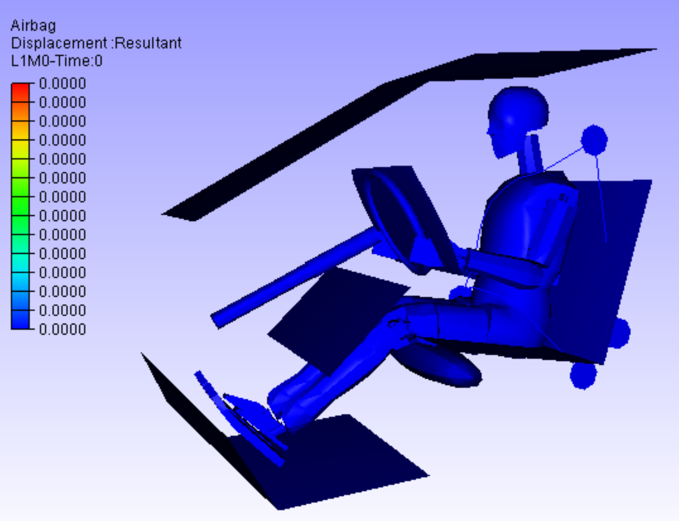
ORTHO_VIEW
This command sets Ortho/Perspective Projection.
ORTHO_VIEW, <Y/N>
[1] bOrtho: Set Y for Ortho, set N for Perspective
Ortho View |
Perspective View |
|
|
ViewPoint Commands
VIEWPATH
This generates a ViewPath with user deifned name.
VIEWPATH, <ViewPath Name>
[1] ViewPath name
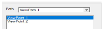
Example
This will create a viewpath by name Sample.
VIEWPATH,Sample
Note
New ViewPath is generated only when ViewPoint is created.
IMAGE_VP
This creates the background and/or other images to be imported into VCollab.
IMAGE_VP, <VPName>, <image file name>, <Title String>, <Title Position(Sx,Sy)>
[1] VPName: ViewPoint name (optional). If VPName=N, then image is set as background and ViewPoint is not created
[2] Image File Name: user should provide image file name
[3] Title String: ViewPoint title name (optional)
[4,5] Title Position(Sx,Sy) : ViewPoint title X and Y position (optional)
Example
Background is created using Sample.png file.
IMAGE_VP,N,Sample.png
ViewPoint named Stress is created with background image as Sample.png. Title VM Stress is also created in ViewPoint at the desired location.
IMAGE_VP,Stress,Sample.png,VM Stress,0.2,0.1
ADD_VP
This creates a ViewPoint with user defined VPName.
ADD_VP, <vpname>, [<Title>, <title position xy>]
[1] ViewPoint name
[2:4] Title, title position xy (optional): It creates title in the VP and places at desired position
Example
It adds a ViewPoint by the name VMStress.
ADD_VP,VM_Stress
It adds a ViewPoint by the name VMStress. Title Stress is added to the ViewPoint at desired position.
ADD_VP,VM_Stress,Stress,0.2,0.1
ADD_VP_ANIM
This creates a ViewPoint with animation.
ADD_VP_ANIM, <vpname>, [<Title>, <title position xy>]
[1] ViewPoint name
[2:4] <Title>, <title position xy> (optional): It creates title in the ViewPoint and places it at desired position
Example
It adds a ViewPoint with animation by the name VMStress.
ADD_VP_ANIM,VM_Stress
It adds a ViewPoint with animation by the name VMStress. Title Stress to the ViewPoint at desired position.
ADD_VP_ANIM,VM_Stress,Stress,0.2,0.1
Set Display Commands
DEL_ENTITY
This command specifies entity types to be deleted.
DEL_ENTITY, PROBE, LABEL, TABLE, 2DLABEL, 3DLABEL, 2DTABLE, XY, SYMBOL, SECTION
Note
This command is used in the beginning of every ViewPoint to clear the data from previous ViewPoint.
SET_DISPLAY
This sets the display mode settings in the VCollab Pro GUI.
SET_DISPLAY, COLOR=Y, LEGEND=Y, DEFORM=Y, UDMESH=1, DMODE=1, AXIS=Y, SECTION=N, BG=1
[1] Color: Sets CAE color plot, Y to apply color plot (optional)
[2] Legend: Show Legend, Y to show the legend (optional)
[3] Deform: Show deformation, Y to show the deformation (optional)
[4] UDMesh: sets visibility for undeformed mesh, valid range is 0 to 3 (optional)
0: Wireframe
1: Transparent
2: Feature Edges
3: Transparent Edge
[5] DMode: Sets display mode of the scene, valid range is 0 to 5 (optional)
0: Shaded
1: Shaded Mesh
2: Wireframe
3: Hiddenline Removal
4: Point
5: Transparent
[6] Axis: Show Axis(Y/N), Y to show the axis (optional)
[7] Section: Show section(Y/N), Y to show the section (optional)
[8] BG: Background, valid range 0 to 2 (optional)
0: Plain
1: Gradient
2: Texture, use command IMAGE_VP to set BG image
Example
Sets the display mode settings according to the mentioned parameters.
SET_DISPLAY,COLOR=Y,LEGEND=Y,DEFORM=N,SECTION=N,AXIS=Y
SHOW_LABEL
This sets the probe label settings.
SHOW_LABEL, ID=Y/N, ROW=Y/N, COL=Y/N, RANK=Y/N, PART=Y/N, HEADER=Y/N, ABR=Y/N, PROBE=0, DISP=Y/N, ARRANGE=0-5
[1] ID: Show node/element id (Y/N), Y to show id (optional)
[2] ROW: Show row header (Y/N), Y to show row header (optional)
[2] COL: Show column header (Y/N), Y to show column header (optional)
[3] RANK: Show Rank (0/1/-1), 0 to hide Rank, 1 to show Rank and -1 to show Rank in ascending order (optional)
[4] PART: Show Part name (Y/N), Y to show Part name (optional)
[5] HEADER: Show Header Legend(Y/N), Y to show Header Legend (optional)
[6] ABR: Display Abbreviations legend, Y to show Abbreviation Legend (optional)
[7] PROBE: Sets current probe type, valid range is 1 to 5 (optional)
1: CurrentResult-Derived
2: CurrentResult-Full
3: All Results-Table
4: All Instances-Table
5: All Instances-XY Plot
[8] DISP: Show labels (Y/N), Y to show labels
[9] ARRANGE: Sets label arrangement mode, valid range is 0 to 5 (optional)
0: Actual.
1: Top-Bottom.
2: Compact
3: Circular
4: Silhouette
5: Rectangular
Example
Sets the probe label settings according to the mentioned parameters.
SHOW_LABEL,ID=N,RANK=Y,PROBE=1
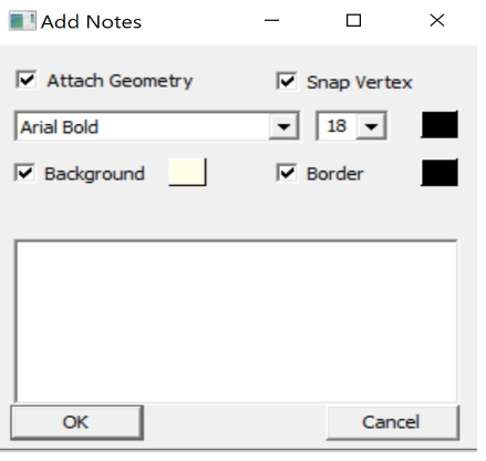
SET_FONT
This sets the font for the entity type as listed.
SET_FONT, <Type>, <Size>, <Name>, <iR,iG,iB> , <ibR,ibG,ibB>, <iborder>
[1] Type: Entity type
NOTE
PROBE_VALUE
PROBE_TEXT
OTHERS
[2] Size: font size
[3] Name: font name
[4:6] iR, iG, iB: font color RGB (0-255)
[7:9] ibR,ibG,ibB: font background color (0-255)
[10] iborder: Border on/off (0=Off else ON)
Example
This will set the note settings according to the parameters with no border.
SET_FONT,NOTE,18,Arial Bold,92,92,92,255,255,240,0
This will set the note settings with default label background with border.
SET_Font,NOTE,26,Arial Bold,36,62,141
Note
Values of <iR, iG, iB> and <ibR, ibG, ibB> are available in Add Notes dialog. User can click on the color and decide on the values accordingly.
SET_MODEL_COLOR
This sets random colors to each part in the model (No arguments).
SET_MODEL_COLOR
No arguments
Legend Commands
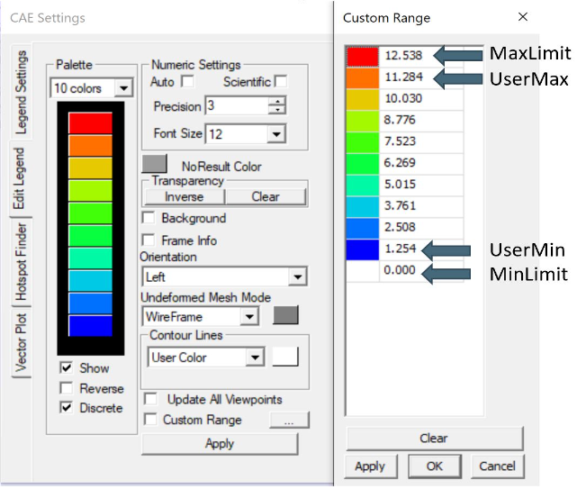
SET_LEGEND
This sets legend settings.
SET_LEGEND,<UserMax> ,<UserMin> ,<MAXLimit> ,<MINLimit> ,<Precision>, <Discrete(Y/N)>, <Reverse(Y/N)>, NColor
[1,2] UserMax, UserMin: Sets Custom Legend Range, set NA to skip limit setting
[3,4] MAXLimit, MINLimit: Legend limits, set NA to skip limit setting
[5] Precision: Sets number of digits required in precision
[4] Discrete: Set Y to display discrete legend
[5] Reverse: Set Y to display reverse legend
[6] NColor: Set number of colors in legend (optional)
[7] All Instances: Set legend for all instances (optional)
Example
This will set the legend settings accordingly.
SET_LEGEND,NA,NA,NA,NA,3,Y,N
LEGEND_HEXCOLORS
This sets the legend colors according to the hexcolors.
LEGEND_HEXCOLORS, <list of hex colors>
Example
LEGEND_HEXCOLORS,FF0000,FFDD00,00FF00,00DDFF,0000FF
SET_LEGEND_DYNRANGE
This sets the values of legend as provided.
SET_LEGEND_DYNRANGE, <list of legend values>
[1:] List of legend values: in descending order
Example
SET_LEGEND_DYNRANGE,20,10,5,2,0
LEGEND_POS
This sets the legend position in the GUI screen.
LEGEND_POS, X_position, Y_position, bRelative (Y/N), iOrientation (0-3/N)
[1] X_pos: Increases from left to right
[2] Y_pos: Increases from top to bottom
[3] bRelative: Y/N, Set Y to set relative to current legend position
[4] iOrientation (0-3/N): Sets orientation (optional)
0: Left
1: Right
2: Top
3: Bottom
N: No change
Example
LEGEND_POS,0.01,0.25
LEGENDFONT_SIZE
This sets the legend font size.
LEGENDFONT_SIZE, <iSize>, <fontName>
[1] iSize
[2] fontName
SET_PALETTE_MODE
This defines the result palette mode when there are merged models.
SET_PALETTE_MODE, <0/1/2/3>
[1] Palette Mode:
0: Active Model
1: Multi Model
2: Combined Model
3: Multi_Common Model
Part Commands
PART_OPTIONS
This command sets the Display Mode and also sets the contour plot mode or material color mode.
PART_OPTIONS, DMODE=(0-5), COLOR=(Y/N), <PartsList>
[1] DMODE=0-5: Display modes
0: Shaded
1: Shaded Mesh
2: WireFrame
3: Hidden Line Removal
4: Points
5: Transparent
[2] COLOR=Y/N: Set Y for contor plot mode, N for material color mode
[3:] Part name list
Example
This will show the all the parts with *Bracket* and *Lever* keywords and will switch on the shaded mode for them.
PART_OPTIONS,DMODE=1, *Bracket*, *Lever*
This will show the all the parts with *Bracket* and *Lever* keywords and will switch on contour plot mode for them.
PART_OPTIONS,COLOR=Y,*Bracket*,*Lever*
PARTS_SHOW
This shows the required Parts in the GUI.
PARTS_SHOW, <ALL/NONE/INVERT/ONLY/ADD>, <Part names list>
[1] Option
ALL: Show all parts
NONE: Hide all parts
INVERT: Invert part show
ONLY: Show Only these parts
ADD: Show these parts
[2:] Part names list
Example
This will show the only the parts with *Bracket* and *Lever* keywords.
PARTS_SHOW,ONLY,*Bracket*,*Lever*
PARTS_HIDE
This hides the required Parts in the GUI.
PARTS_HIDE, <ALL/INVERT/ONLY>, <Part name list>
[1] Option:
ALL: Hide all parts
INVERT: Invert part hide
ONLY: Hide Only these parts
[2:] Part name list
Example
This will hide the only the parts with *Bracket* and *Lever* keywords.
PARTS_HIDE,ONLY,*Bracket*,*Lever*
ASM_SHOW
This sets assembly show/no show.
ASM_SHOW, <Y/N>, <Assembly Names>
[1] bAsmShow: Y/N, Set Y to show
[2:] Assembly names
FILTER_PARTS
This command filters the parts based on results in the GUI screen.
FILTER_PARTS, fMin, fMax, <bFitView(Y/N)>
[1] fMin: Min result limit for filtering parts or NA can be provided
[2] fMax: Max result limit for filtering parts or NA can be provided
Both fMin and fMax cannot be NA, atleast one limit should be provided
[3] bFitView (Y/N): For a fit view of filtered parts (optional)
Result Commands
SEL_RESULT
This selects the result to be displayed in GUI.
SEL_RESULT, <Result Name>, <Instance>, <Derived Type>
[1] Result Name: Selects the name of the result to be displayed
[2] Instance: Selects the instance of the result to be displayed
[3] Derived Type: Selects the derived type of the result to be displayed
By default, Derived type is NA
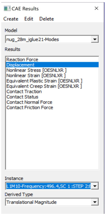
Example
This will select the Max Principal Stress result for L3M1 instance.
SEL_RESULT,*Stress*max*prin*,L3M1,NA
SEL_INSTANCE
This selects the instance for current result.
SEL_INSTANCE, <InstFlag>
[1] Instance Flag:
0: Last Instance
1: Max Instance
2: Min Instance
3: First Instance
Else Current Instance
CREATE_RESULT
This creates the new result from the existing result.
CREATE_RESULT ,<New Result Name>, <Result A>, <Result B>, <Equation with A and B>
[1] New Result Name
[2] Result A name: for the expression
[3] Result B name: for the expression
[4] Arithmetic expression or formula with variables A and B
Example
This creates a max result from result A and B.
CREATE_RESULT,Name,A,B,IF((abs(A)>abs(B)),A,B)
CREATE_ENVELOP
This creates Max/Min envelope result.
CREATE_ENVELOP, <sResult>, <sDerived>, <bIsMax(Y/N)>
[1] sResult: Required result for creating envelope
[2] sDerived: Derived type for the result or NA can be used for default
[3] bIsMax: Y/N, Set Y for Max envelope(default) and N for Min envelope (optional)
CREATE_RESULT_CYL
This creates a cylindrical co-ordinate result for the selected result.
CREATE_RESULT_CYL, RefResult, NewResult, <Origin(XYZ)>, <XDir(xYZ)>, <YDir(xyz)>, U/All
[1]: VCollab Result name
[2]: New result name
[3:5]: Origin of the new coordinate system
[6:8]: X axis vector
[9:11]: Y axis vector
[12]: Component name can be empty or any one of the following
For Vector Result: "U","V","W"
For Tensor Result: "S11","S22","S33","S12","S23","S13"
Example
This creates a new cylindrical result Disp Radial with origin at <53.66 73.05 42.747>.
Displacement,Disp Radial, 53.66, 73.05, 42.747, 1, 0, 0, 0, 1, 0, U
NEW_INSTANCE
This command creates instance using expression.
NEW_INSTANCE, Result, InstA, InstB, Expression, sNewInst
[1]: VCollab Result
[2]: Instance A name for the expression
[3]: Instance B name for the expression
[4]: Arithmetic expression or formula with variables A and B
[5]: New Instance Name
Example
This creates a new instance by the name MaxDamage from the Damage instance L1M1 and L2M1.
NEW_INSTANCE,Damage,L1M1,L2M1,Max(A,B),MaxDamage
NodeSet Mask Commands
RES_MASK
This creates a NodeSet from the selected result for masking.
RES_MASK, <mask name>, <result name>, <n Adj>, <min> ,<max>
[1]: User Defined NodeSet name
[2]: VCollab Result name
[3]: Number of adjacent layer to mask (optional)
[4]: Minimum range value to get the nodes within the result (optional)
[5]: Maximum range value to get the nodes within the result (optional)
Example
This will create a NodeSet CPMask based on Contact Pressure masking limits.
RES_MASK,CPMask,Contact Pressure,1,0.01,1000
PART_MASK
This creates NodeSet from the selected parts for masking.
PART_MASK, <maskname>, <partname>, <Proximity dist>, <n Adj>
[1]: User defined Node set name
[2]: Part name to be masked
[3]: Proximity of the nodes to be added to the NodeSet
[4]: Number of adjacent layer to be masked
Example
This will create a NodeSet BracketMask based on the nodes in *B*EXCLUDE parts. 1 layer of adjacent nodes is also added to the masking NodeSet BracketMask.
PART_MASK,BracketMask,*B*EXCLUDE,NA,1
NODE_MASK
This creates NodeSet from the selected nodes.
NODE_MASK, <maskname>, <Radius>, <nodelist>
[1] maskname: User defined Mask Name
[2] Radius: The nodes within this range are added to the NodeSet, it should be floating value
[3] nodelist: list of nodes ids for masking
Example
This will create a NodeSet NodeMask based on the nodeslist 11234, 3456.
NODE_MASK,NodeMask,15.0,11234,3456
SET_MASK_MODE
This sets the mode of the masking node sets.
SET_MASK_MODE ,<MODE>, <mask name list>
[1]: Mode can be 0/1/2
0: N/A
1: In
2: Out
[2:] Mask name list: can be the NodeSet names available for masking
SET_MASK
This sets the mode of the masking node sets to IN.
SET_MASK_IN ,<mask name list>
[1:] Mask name list: can be the NodeSet names available for masking
SET_MASK_IN
This sets the mode of the masking node sets to IN.
SET_MASK ,<mask name list>
[1:] Mask name list: can be the NodeSet names available for masking
Hotspot Commands
PROBE_RES
This creates a list of results to be displayed in probe label.
PROBE_RES, <ProbeResultList>
[1:] List of results to be added to the probe labels
Example
This will create a list of VonMises and Max Principal Stress when probing.
PROBE_RES,*Stress*von*mis*,*Stress*Max*prin*
HS_LIMITS
This command sets the Hotspot Dialog Parameters.
HS_LIMITS, <filter range: min, max>, <nTop>, <nBottom>, <ZoneRadius>
[1]: Sets minimum range value
[2]: Sets maximum range value
[3]: Number of top hotspots
[4]: Number of bottom hotspots
[5]: Defines the zone radius for hotspots
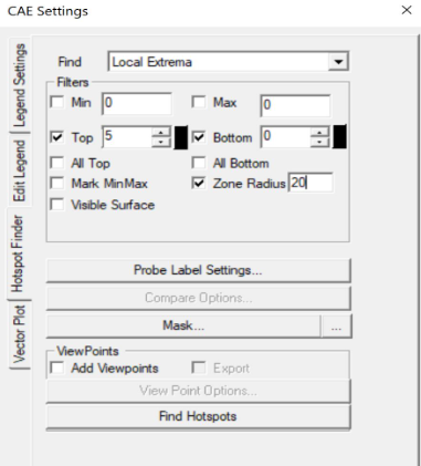
Example
This will set the hotspot dialogue box parameters.
HS_LIMITS,NA,NA,5,0,20.0
HOTSPOT_VIEW
This creates a ViewPoint with the given hotspots settings.
HOTSPOT_VIEW, <sVPName>, <Hotspot Params>
[1] sVPName: ViewPoint name
HS Parameters:
[2]: Sets minimum range value
[3]: Sets maximum range value
[4]: Number of top hotspots
[5]: Number of bottom hotspots
[6]: Zone radius for the hotspot
Example
This will create new ViewPoint named Hotspots VP with top 5 hotspots and zone radius of 20.
HOTSPOT_VIEW,Hotspots VP,NA,NA,5,0,20.0
COMP_HOTSPOTS
This computes the hotspot with NodeSet masking.
COMP_HOTSPOTS, sVPName, Masklist
[1]: ViewPoint name, Set 'N' for not adding ViewPoint
[2]: NodeSets name for masking
If no parameters are given, it will find the hotspot in the GUI and ViewPoint needs to saved using ADD_VP command
LOADCASE_HSVIEW
This creates hotspot view for each instance.
LOADCASE_HSVIEW,<VPathName> ,<iFirstInstance>, <iLastInstance>
[1]: ViewPath name (optional)
[2]: Starting Instance (optional)
[3]: Ending Instance (optional)
If no parameters are provided then, hotspot view for all instances will be generated for the displayed result
Example
This will create new hotspot ViewPoints in ViewPath for instances 5 to 9.
LOADCASE_HSVIEW,sVPathName,5,9
HEADER_POS
This sets the location for header legend (set before PROBE_RES call).
HEADER_POS, <Screen_Xpos>, <Screen_Ypos>
[1]: Screen Xpos (optional)
[2]: Screen Ypos (optional)
[3]: Ending Instance (optional)
If no parameters are provided then, the Screen_Xpos and Screen_Ypos are set to 0.05 and 0.7
SET_COMPARE_RES
This sets the Hotspots compare settings.
SET_COMPARE_RES, <ON=Y/N>, <BY=0-2>, <MODE=0-2>, <WITH=0-2>, <RADIUS=5.0>, <SHOWALL=Y>, <B2A=Y/N>
[1] ON=Y/N: Y to set hotspots compare option ON
[2] BY=0-2: Sets Comparison of Results mode, valid Range 0-2
0: Same Result Name
1: Selected Results Order
2: Result's Display Name
[3] MODE=0-2: Sets comparison mode, valid range 0 to 2
0: For Same Part
1: For Current Visible Parts
2: For All parts
[4] WITH=0-2: Sets comparison, valid range 0 to 2
0: For Same Part
1: For Current Visible Parts
2: For All parts
[5] RADIUS: Float value, sets a radius to compare hotspots within a sphere
[6] SHOWALL=Y/N: If set to Y, sets additional label lines to compared node/element of other models
[7] B2A=Y/N: If set to Y, finds hotspots in all models and compares across all models. If set to N, find Hotspots only in the current model and those Hotspots are used to compare across all models.
Example
This will set the result compare settings accordingly.
SET_COMPARE_RES,ON=Y,BY=0,MODE=1,WITH=0,RADIUS=5.0,SHOWALL=Y,B2A=N
HS_TABLE2D
This command creates a hotspots summary table.
HS_TABLE2D,<ScreenX>, <ScreenY>, <Header strings>
[1] ScreenX: X position of table in screen
[2] ScreenY: Y position of table in screen
[3:] Header text for table fields
Example
HS_TABLE2D,0.1,0.6,NodeID,VonMises,StressMaxP
Auto View Commands
ALL_RESULT_VPS
This command computes hotspots and creates a ViewPoint. If Modal result is available it creates one Modal ViewPoint.
ALL_RESULT_VPS, <nhotspots>
[1]: Number of Hotspots
Results with name <Thickness Bottom Material Force Volume Constraint> are not considered
Example
ALL_RESULT_VPS,5
MODAL_VPS
If Modal data is available this command creates Modal views else it creates hotspot views for each result.
MODAL_VPS, <no of modes>, <summary table=Y/N>
[1]: Number of mode case
[2]: Creates a mode case table if set to Y
Example
MODAL_VPS,5,Y
COMPARE_GEOM_VPS
This command finds the difference between the two model's geometry (Merged models) and creates the ViewPoints.
COMPARE_GEOM_VPS, <compare mode>, <max search distance>
[1]: Sets compare mode, valid range 0-2
0: Same Parts
1: Visible Parts
2: All Parts
[2]: Two model points are compared within this value, geometry deviation more than this value is ignored
Example
COMPARE_GEOM_VPS,1,20
ENVELOP_VIEW
This command creates a CAE envelope result for transient or multi-instances data and creates hotspot view.
ENVELOP_VIEW, <sResultStr>, <hotspot parameters>
[1]: Result name for the envelop result
HS Parameters list (optional):
[2]: Sets minimum range value
[3]: Sets maximum range value
[4]: Number of top hotspots
[5]: Number of bottom hotspots
[6]: Zone radius for the hotspot
hslimits: None, If the user does not want to change the Hotspot settings
DelInst: Instance name that is to be deleted(optional)
Example
ENVELOP_VIEW,*von*Mises*,NA,NA,5,20.0
EXPLODE_VIEW
This command sets parts in an exploded view.
EXPLODE_VIEW, <Y/N>, <Percentage(0-100)>
[1]: Y/N, Set Y for Explode and Reset, Set N for just Explode
[2]: Percentage value of current explode, it should be >0 and <=100
XY Plot Commands
MINMAX_PLOT
This command creates Min-Max XYPlot for current result.
MINMAX_PLOT, <Plot Name>, <iMinmax>
[1] Min max Plot name
[2] iMinmax: Index of curve to be created
0: Max curve(default)
1: Min curve
2: Both min and max curves
HS_XYPLOT
This command computes hotspots and creates Transient XY plot with curves for selected number of hotspots.
HS_XYPLOT, <Plot Name>, <MaxHS>
[1] XY Plot name
[2] MaxHS: Max number of hotspots/curves
SETXYPLOT_WIN
This command sets the XY plot background and windows size.
SETXYPLOT_WIN, <bgColor(rgb)>, <winsize(xmin,ymin,xmax,ymax)>
[1:3]: XY Plot background colors RGB(0 to 1)
[4:6]: XY Plot window size(xmin,ymin,xmax,ymax)
IMPORT_XYCSV
This command imports the result from CSV File in XYPlot.
IMPORT_XYCSV, <csvfile>
[1]: CSV file path
Other Commands
ADD_2DNOTE
This command adds a 2d note in the ViewPoint.
ADD_2DNOTE, <Note String>, <2D position(x, y)>
[1]: Note text
[2]: X and Y normalized position in GUI(0 to 1)
Example
ADD_2DNOTE,Title Page,0.4,0.3
SET_ANIM
This command sets animation type and settings.
SET_ANIM, <Type>, <nFrames>, <bStaticFringe(Y/N)>, <Scale factor>, <Speed>
[1] Type: Animation type, valid values 0/1/3
0: Linear
1: Transient
3: Harmonic
[2] nFrames: Sets number of frames (instances)
[3] bStaticFringe: Set Y for Static fringe (same legend for all animation frames)
[4] Scale factor: Sets scale factor based on bounding box. Deformation percentage is with respect to geometry size
[5] Speed: Set delay value to slow animation in milliseconds, valid range 0 to 100 and 100 sets max speed
Example
SET_ANIM,1,20,Y,3,20
ARRANGE_MODEL
This command arranges the models in a row.
ARRANGE_MODEL, <Nrow>
[1] Nrow: Number of rows to arrange models. If Nrow<0, it resets the model.
RUN_SCRIPT
This command runs a script file with given arguments.
RUN_SCRIPT, <ScriptFile>, <bReUse(Y/N)>, <FunctionName>, <Arguments..>
[1]: Script file path
[2]: Set Y to reuse module(optional)
[3]: Function name in script to be executed
[4:]: Arguments for the function
Example
RUN_SCRIPT,E:\Userlocation\sample.py
PYRUN
This command runs VCollab API function call.
PYRUN, <One line Python Script>
[1] <One line Python Script>: VCollabAPI function with all its required arguments as strings
Example
PYRUN,.xSetPartColor("spot","PSHELL PID_114",255,0,0,1)
PYSGRUN
This command Runs VCollab API function call and displays result in a popup for debugging.
PYSGRUN, <One line Python Script>
[1] <One line Python Script>: VCollabAPI function with all its required arguments as strings
Example
PYSGRUN,.pxGetCAECurrentResult("")
EXIT
This command stops execution of command list. All further commands are not executed.
EXIT
No arguments