How to View Cut sections in VCollab Presenter?
The users of VCollab Presenter can create and view cut section planes
Steps to view the cut section
Load any CAX model in VCollab Presenter.
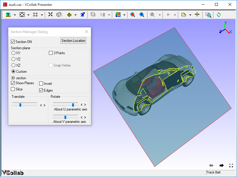
Click Cut Section in the context menu to open the Section Manager dialog
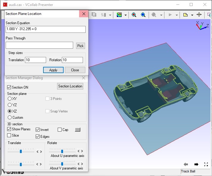
Click XY, YZ, XZ options to view section planes parallel to coordinate planes and passing through the model center.
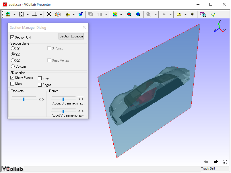
Model is clipped with respect to the section plane defined.
Click Show Planes to view a semi transparent section plane.
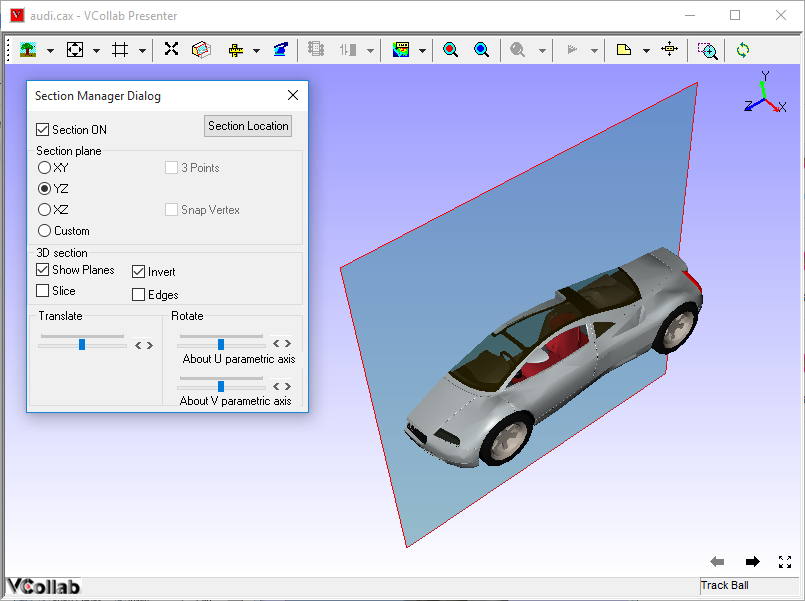
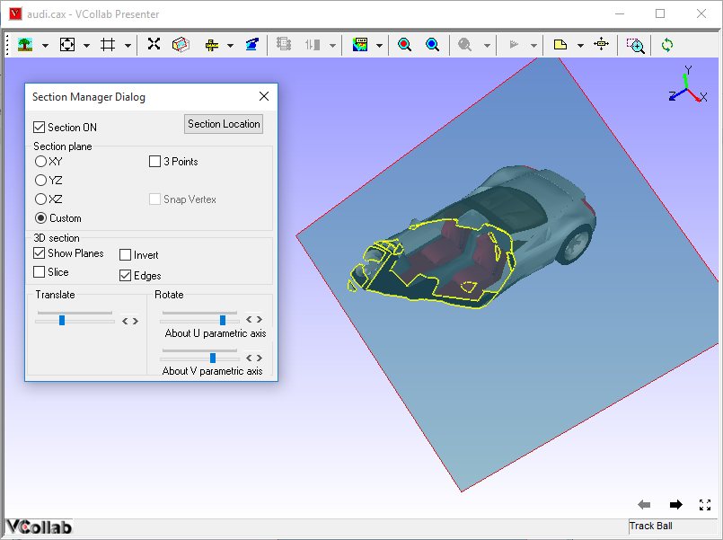
Click Invert to invert clipping side.
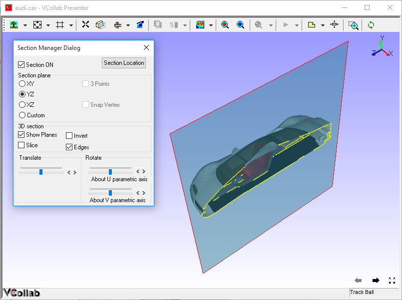
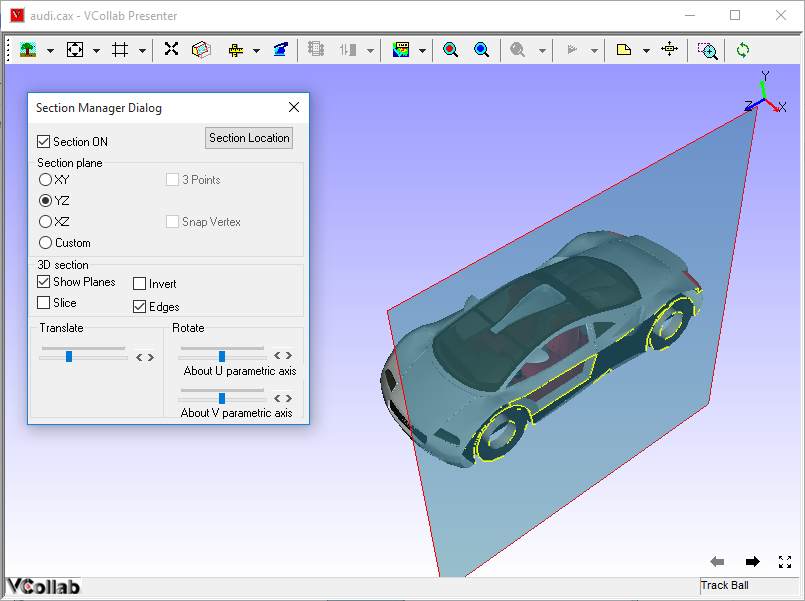
Click Edges to view the intersection on model to the plane.
Use Translation slider control or scroll button near the slider control to translate section plane in normal direction.
Use Rotation slider controls or scroll buttons near slider controls to rotate section planes in either U or V Parametric Axes of the plane.
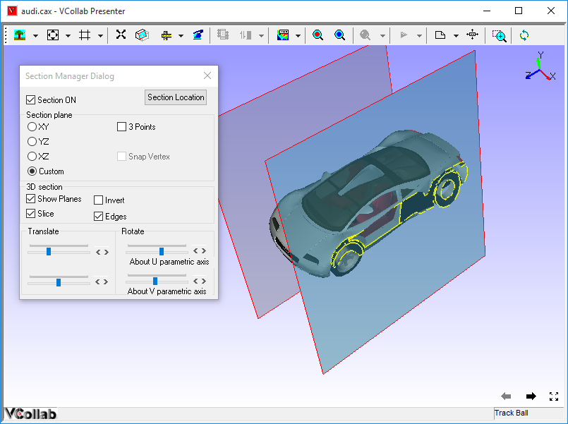
Click Slice to add one more cut section plane in the opposite clipping direction.
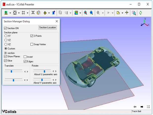
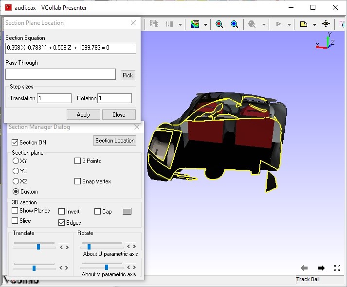
Click Custom to create a user defined section plane.
How to set user defined section plane
Click Custom in the Section Manager dialog.
Click the 3 Points option which is now enabled.
Click any three points on the model.
Section plane, passing through the points selected, is thus defined.
Use Snap Vertex to select the nearest vertices of the model.
How to get and edit section plane location
Click Section Plane location in the Section Manager dialog to openSection Plane Location dialog.
It displays the current primary section plane equation in the form of aX+bY+cZ+d=0. where (a,b,c) is unit normal of the plane and d refers to the perpendicular distance of the plane from origin.
Users can enter any point coordinates or pick a vertex using the Pick button to move the plane to a particular point.
How to set unit increment for the slider controls
Click Section Plane Location in the Section Manager dialog to open the Section Plane Location dialog.
Change Translation and Rotation step sizes provided.
Click Apply to set values and reset the slider positions.
By default, the translation slider is split into 100 ticks.
Users can change the translation step size from 1 to 100.
By default, rotation sliders are split into 180 ticks, which means each tick refers to one degree.
Users can change the rotation step size from 1 to 180.
Notice the changes made to the number of tick marks and position of sliders.