Creating and Editing Cut-Section
VMoveXGUI provides the ability to create cut-sections.
This module details the steps for creating cut-sections.
Load the CAE file
In this example Gold.case file provided in the Samples/Case/in/gold directory is used.
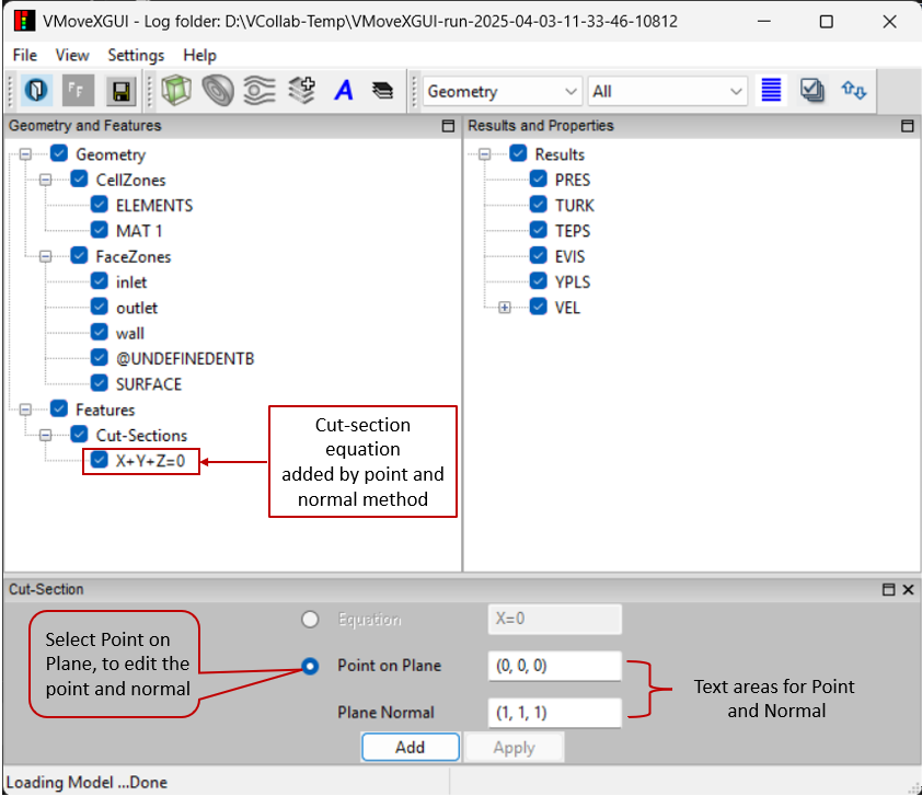
Click on the Add Cut-Section icon to create cut-sections.
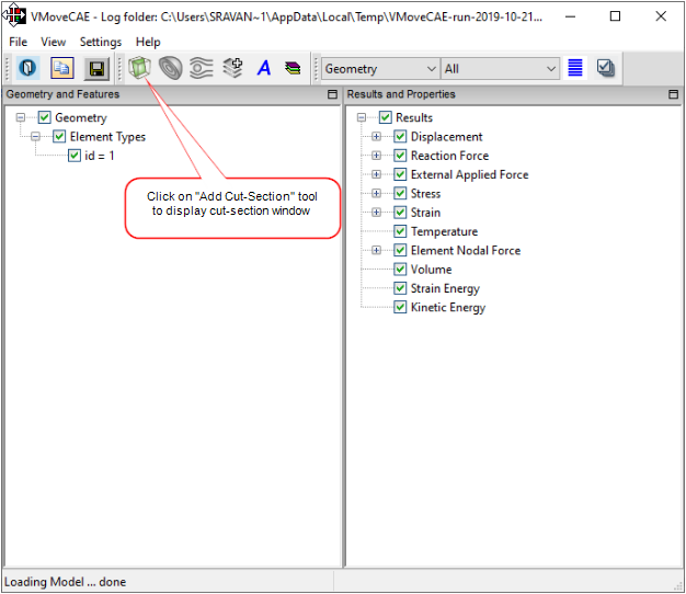
This brings up the cut-section window.
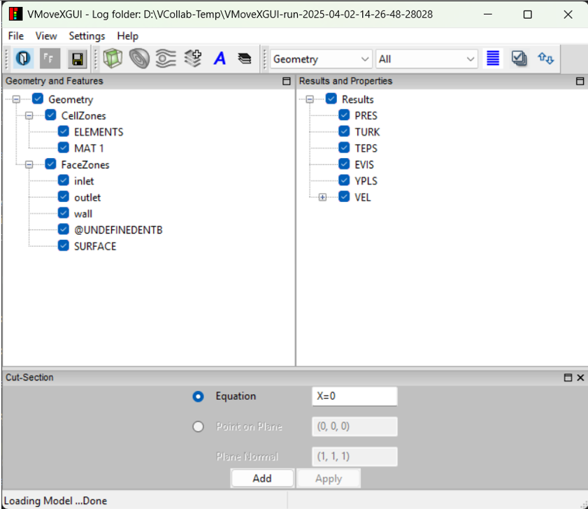
Add a cut-section: A cut-section can be created in two ways:
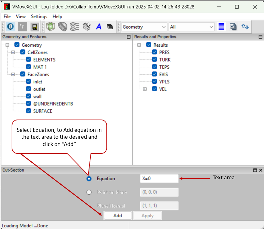
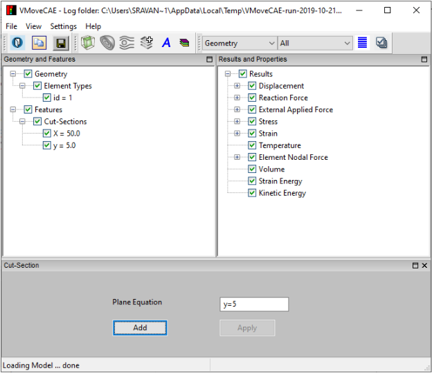
Using an Equation: Enter the equation and click Add. The cut-section equation must be in the form of “AX+BY+CZ=D”.In this example, we have entered “X=0”.
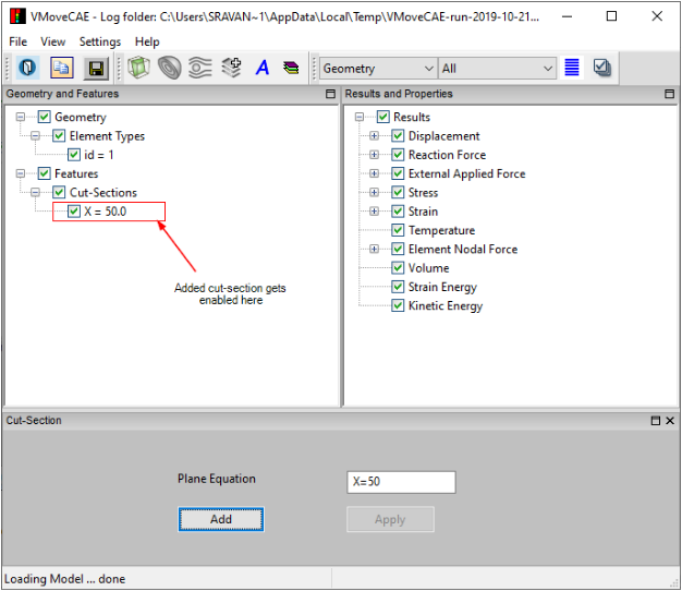
The new item gets added to the Cut-Sections tree under Features.
Using a Point and Normal: Specify a point (X, Y, Z) and a normal vector (A, B, C). The equation for the cut-section is automatically generated.In this example, we have entered the point (0,0,0) and normal (1,1,1). This will generate the equation “X+Y+Z=0”.
More cut-sections can be added in a similar way. For example, another cut-section with “Y=0” can be added.
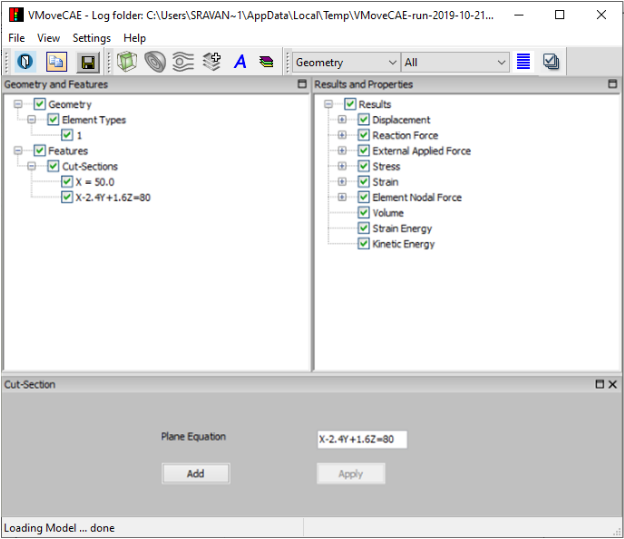
An existing cut-section can be changed by changing its Plane Equation.
Select the cut-section “Y=0” and change the value to “X+Y=0”.
Proceed to translate to CAX file by clicking on Save CAX icon. The output CAX file can be opened in VCollab Professional or VCollab Presenter to visualize the file cut-sections. If any cut-section is out of bounds and not cutting the geometry then VMoveXGUI ignores it and the cut-section will not be created.