How to Create and Edit Flow Lines?
VMoveCAE provides the ability to create streamlines and particle-trace. This support is limited to steady flows only. This module shows the steps for creating streamlines and particle-traces.
Start VMoveCAE and load a CFD file.
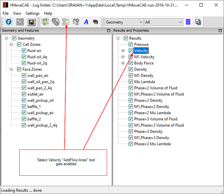
Select Velocity from the Results and Properties tree to enable the Add Flow-Lines icon from the toolbar.
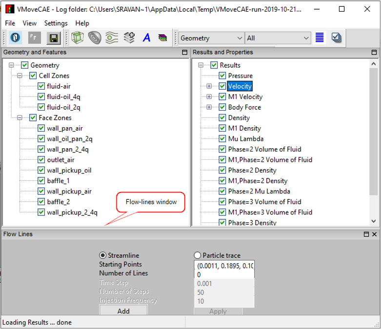
Click on the Add Flow-Lines icon to open the Flow Lines window.
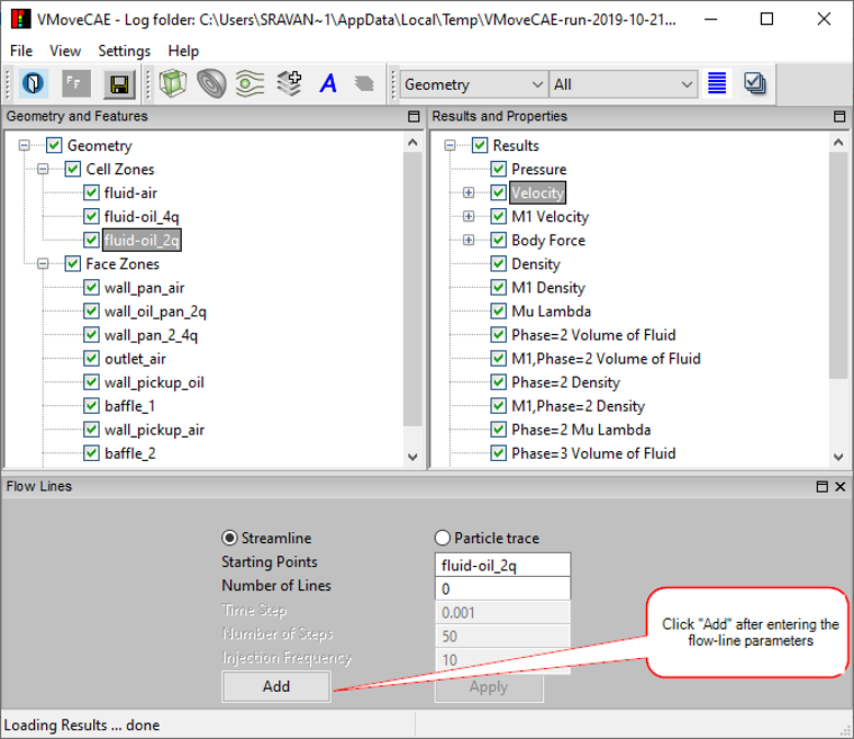
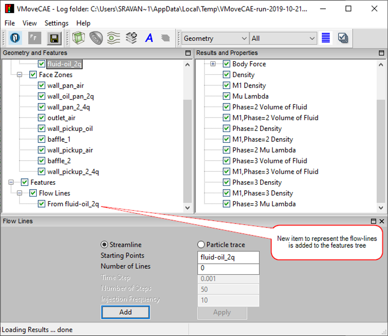
Set the flow-line parameters and click Add. This adds a new flow-line in the “Features” tree in “Geometry and Features” window.
Note: For Starting Points, users can either provide a single point, or select a part from the “Geometry and Features” tree. When a part is selected, VMoveCAE uses the centroids of the part’s faces as flow-line starting points. Particle traces require additional inputs such as time-step, number of steps in the animation and injection frequency (Ex. injection frequency of 10 means particles are injected at the starting points every 10 steps).
Click on the Save CAX icon to translate and create a CAX file. Open it in VCollab Pro or Presenter to visualize the added flow-line. For better flow-line visualization, users can make the parts transparent.