Measurement
The procedures to measure distance between 2 points and measuring the arc lengths are explained here. Users can measure the following:
Distance Measurement
Arc Measurement
Vertex Info
Export to CSV
Polygon Area
Note
Fonts of measurement labels can be modified using Label Settings dialog.
Polygon area function works well only for polygon defined in a plane.
Measure Options
3D Distance
Point to Point
Point to Edge
Point to Face
Arc
3 Point Arc
Snap Vertex
Vertex Info
Polygon Area
This helps user to measure shortest 3D distance between two points on the model. Annotation labels with measured value will be attached to the dimension lines.
User can measure the linear distance in the following ways,
Point to Point : Measures distance between two user picked points.
Point to Edge: Measures shortest distance between point and the edge picked by user.
Point to Face: Measures shortest distance between point and triangle picked by user.
Point to Point
Click the icon
 from toolbar.
Click 2 points of interest on the model to measure the distance.
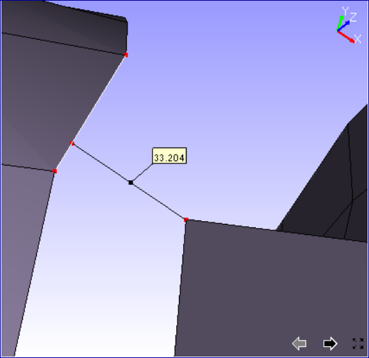
The points clicked are highlighted in red color and a line is drawn between the end points
An annotated label with distance value is attached to the middle point of line drawn.
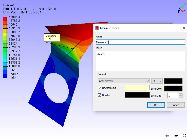
Double clicking on the measure allows to format the label data and renaming the measure name.
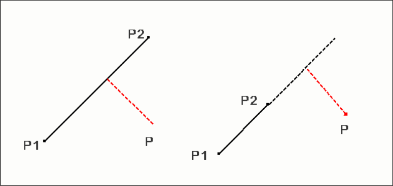
Point to Edge
Click 'Point to Edge'.
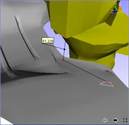
Click a point on a model and click on a model for closest triangle edge.
The point and the closest edge will be highlighted in red color. Edge is extended if foot of perpendicular does not lie in the edge segment.
An annotated label with distance value is attached to the middle point of line drawn.
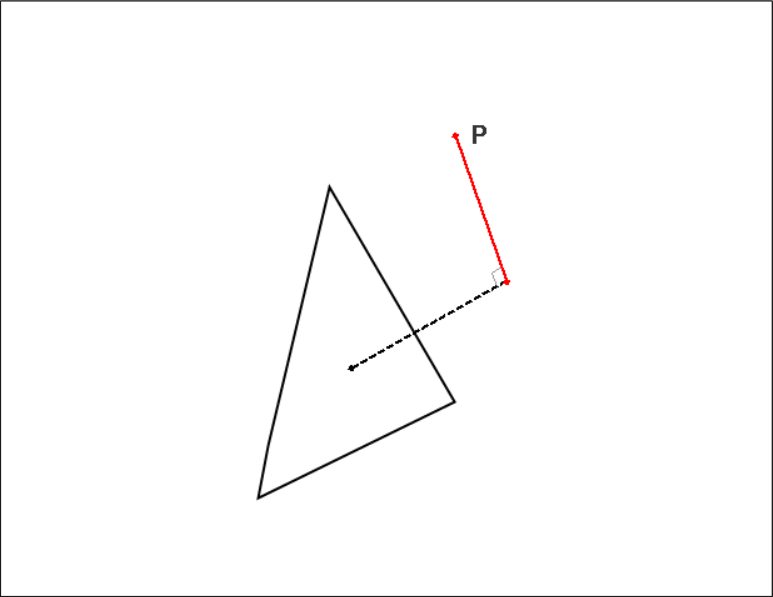
Point to Face
Click 'Point to Face'.
Click a point on a model and click on a model triangle.
The point and triangle points will be highlighted in red color.
An annotated label with distance value is attached to the middle point of line drawn.
Arc Measurement
Click down arrow near measure icon
in toolbar.Click '3PointArc' option.
Click on 3 points of interest on the model.
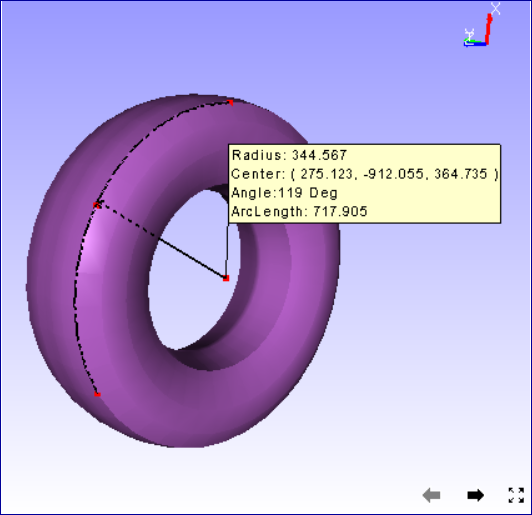
An arc is drawn from first point to third point passing through the second point.
All three points are highlighted in red color.
An arrow is drawn from center of arc to the curve to denote the radius.
An annotated label with arc information is attached to the center of arc.
Curve hidden behind the model is drawn with dashed lines.
Snap Vertex
User has to pick points in the model for measuring.
Using this 'Snap Vertex' option, user can pick the nearest vertex in the model.
It helps user to measure with extended accuracy.
Click 'Snap Vertex' in the drop down menu to enable this option.
Vertex Info
Click 'Vertex Info' in the drop down menu to enable this option.
Click on the model.
The coordinates of the clicked position is displayed in a label.
This label is temporary and is cleared on users next click.
User can not save this label into viewpoint.
This option helps in measure and section modules.
Export to CSV
This function helps user to export all visible measurement data into a csv file.
User can achieve this either through "Tools | Measurement | Export to CSV" in menu bar or "Measure | Export to CSV" in context menu.
Sample CSV file
# Application Name: VCollab Pro X
# Application Version: 4.12.121.605
# Date & Time : 21-10-2021, 18:43:30
# Current User : karuna
# Measure Name, Measure Value, Model Name 1, Model Name 2, Node ID 1,X1,Y1,Z1, Node ID 2,X2,Y2,Z2
Measure 1,43.046,body1,Fadjuster,NA,-13.8797,-19.9479,41.2141,NA,-0.179211,3.7484,7.99158
Measure 2,31.718,body2,Fbody,NA,22.7075,-18.5456,32.922,NA,4.77808,-33.8141,11.6751
|
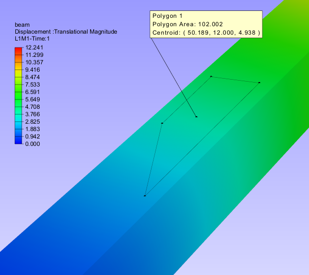
Polygon Area
User can define a polygon by points in a plane of the model and get the area value in a label. This helps user to compute the concentration of results in a particular zone.
Note
This function works well only for polygon defined in a plane.
Steps to measure a polygon area
Go to Tools | Measurements module
It expands with a submenu
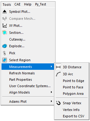
Select Polygon Area option. This enables mouse mode to pick points in the model.
Go to the viewer and click on the model to select points.
Select at least 3 points to define a polygon.
Right click or click on empty area to generate polygon area label.
Label displays Area and centroid of the polygon.
Make sure that all points selected are coplanar.